Introduction
So... how do I use a multimeter? This tutorial will show you how to use a digital multimeter (DMM), an indispensable tool that you can use to diagnose circuits, learn about other people's electronic designs, and even test a battery. Hence the 'multi'-'meter' (multiple measurement) name. The most basic things we measure are voltage and current. A multimeter is also great for some basic sanity checks and troubleshooting. Is your circuit not working? Does the switch work? Put a meter on it! The multimeter is your first defense when troubleshooting a system. In this tutorial we will cover measuring voltage, current, resistance and continuity.
What is a Multimeter?
A multimeter, also known as a volt-ohm meter (VOM), is an electronic measuring instrument used to measure various electrical quantities. It combines several functions into a single device, allowing users to measure voltage, current, and resistance in electronic circuits.
The basic components of a typical multimeter include:
- Display: A digital or analog screen that shows the measured values. Digital multimeters (DMMs) have a digital numerical display, while analog multimeters use a needle or pointer on a scale.
- Selector Switch: This switch allows users to select the desired measurement function, such as voltage, current, or resistance. It usually has several positions corresponding to different measurement ranges.
- Probes: Multimeters come with two detachable probes, namely a red probe and a black probe. These probes have insulated tips that are used to make electrical connections with the circuit being measured.
- Input Jacks: The multimeter has separate input jacks to plug in the red and black probes. The jacks are color-coded and labeled for specific functions, such as voltage (V), current (A), and resistance ().
- Function Buttons: Some multimeters have additional function buttons that allow users to perform specific operations, such as selecting AC or DC voltage, setting the range, or holding the displayed value.
- Battery Compartment: Multimeters are powered by batteries, and the battery compartment is usually located on the back or bottom of the device. It allows for easy replacement of the batteries when needed.
- Fuse: To protect the multimeter from excessive current, there is often a fuse located inside the device. The fuse will blow if the current exceeds a certain threshold, preventing damage to the multimeter.
These are the fundamental components you will find in most multimeters. However, there can be additional features and components depending on the specific model and advanced functionalities, such as capacitance measurement, frequency measurement, diode testing, and transistor hFE testing.
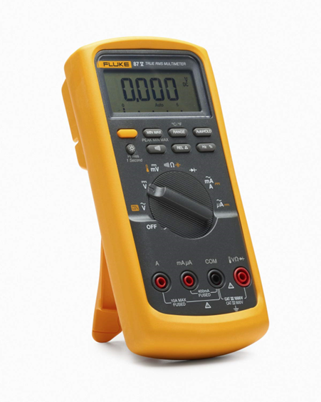
There are many different kinds available in the market, starting from basic pocket multimeters to benchtop ones. The most commonly used ones are called “Hand held” multimeters as they are literally hand held and used. You can, however, find some with a stand which can prop these on a table for easy viewing. The benchtop variety is another kind; it's heavy and always placed on a workbench but with much more accuracy and generally runs on mains electricity.
Fluke is often refreed to as the industry standard for meters, Fluke87 is the most prefered handheld meter for industry and professionals, there are others like Keysight who are also very good
For benchtop meters keithley is considered to be the best, they are most often used to measure critical and high accuracy requirement stuff in production environments as they have lot of automation and remote operation capabilities.
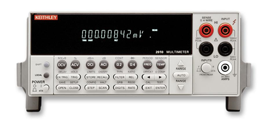
Being aware of the top brands will always give you knowledge on the best avaialbe features and performance. Letting you choose wisely even if you go for a more mainstream brand like Unit-T or Tenma etc.
A multimeter is a versatile device that offers several functions to measure different electrical quantities. Let's explore the various functions commonly found on a multimeter:
- Voltage (V): The voltage function allows you to measure the potential difference between two points in an electrical circuit. Multimeters can measure both AC (alternating current) and DC (direct current) voltages. You can select the appropriate voltage range to measure low or high voltages accurately.
- Current (A): The current function enables you to measure the flow of electric charge in a circuit. Multimeters can measure both AC and DC currents. You can select different current ranges based on the expected magnitude of the current you are measuring.
- Resistance (): The resistance function is used to measure the resistance of a component or a circuit. It helps determine how much a material or device resists the flow of electric current. Multimeters provide various resistance ranges to measure a wide range of resistances accurately.
- Continuity: The continuity function is a handy feature that helps you check if a circuit is continuous or if there is a break in the circuit. When the probes of the multimeter are touched to two points in a circuit, the multimeter emits a beep or shows a visual indication if there is low resistance, indicating a continuous path.
- Diode Testing: The diode testing function allows you to test diodes and other semiconductor devices. It helps determine if a diode is functioning properly or if it is faulty. In this mode, the multimeter applies a small current to the diode and measures the voltage drop across it.
- Capacitance (F): Some multimeters offer a capacitance function, allowing you to measure the capacitance of capacitors in farads (F). This function is useful for testing and troubleshooting capacitors in electronic circuits.
- Frequency (Hz): Certain multimeters have a frequency function that enables you to measure the frequency of an AC signal. This is particularly useful for working with oscillators, generators, or troubleshooting electronic systems that involve time-varying signals.
- Temperature (°C/°F): Advanced multimeters may have a temperature function that allows measurement of temperature using a temperature probe or thermocouple. This feature is useful for applications where temperature monitoring is essential.
- Duty Cycle (%): Some multimeters offer a duty cycle function, which measures the ratio of on-time to the total period of a signal. This is often used in applications like pulse-width modulation (PWM) or signal analysis.
- Transistor Testing: Certain multimeters come equipped with a transistor testing function, enabling you to test the gain (hFE) of transistors and identify faulty ones. But you generally find them on cheap Chinese ones and not really good ones. These are not very accurate hFE measurements.
Most multimeter disasters happen when you accidentally move the selector switch to current measurement mode and try to measure a voltage in a live circuit. This will result in short circuiting the circuit and consequently destroy both the meter and the circuit. Always ensure you’re in the voltage mode when testing a live circuit. For measuring current, always put the meter in series with the circuit being measured before powering the circuit on and then put the meter in current mode. Some meters even have covers installed on the current jacks to ensure you don’t accidentally plug the probes into them while in a voltage measurement mode.
It's important to note that not all multimeters have all of these functions. The availability of specific functions may vary depending on the model and brand of the multimeter.
Safety Precautions
- When working with a multimeter or any electrical equipment, safety should always be a top priority. Here are some essential safety precautions and best practices to follow:
- Familiarize Yourself with the Equipment: Read the user manual and become familiar with the specific features, functions, and limitations of your multimeter. Understanding how to operate it correctly will help minimize risks.
- Personal Protective Equipment (PPE): Wear appropriate personal protective equipment, such as safety goggles, insulated gloves, and non-conductive footwear, especially when working with high voltage circuits.
- Verify Multimeter Functionality: Before each use, check that your multimeter is functioning properly. Ensure the battery is sufficiently charged, and the leads and probes are in good condition without any exposed wires or damaged insulation.
- Voltage Category and Range: Determine the voltage category and range of the circuit or device you are measuring. Ensure that your multimeter is suitable for the voltage level you will be working with. Higher voltage categories require special precautions. High voltage measurements with a cheap Chinese meter are a strict "No-no." Always carefully see for what maximum voltage the meter is certified, this is not the same as having the voltage in the range selector.
- Power Off and Disconnect: Before connecting or disconnecting the multimeter probes to a circuit, ensure that the power is turned off. This reduces the risk of electric shock and damage to the equipment.
- Avoid High Voltage or Current: Never attempt to measure voltage or current levels that exceed the multimeter's specified limits. Doing so can damage the multimeter and pose a safety hazard. Use range selection to match the expected values.
- Use Proper Measurement Techniques: Properly connect the multimeter probes to the circuit or component being measured. Ensure a secure and reliable connection, and avoid touching the probes or conductive parts of the circuit with your bare hands during measurements.
- Insulation and Isolation: Handle and hold the multimeter by its insulated casing or designated areas. Avoid touching the metal parts of the probes when they are inserted into the live circuit. This helps prevent electric shock.
- Beware of High-Energy Sources: Be cautious when measuring circuits that may have stored energy, such as capacitors. Discharge them properly and take appropriate safety measures to avoid accidental shocks.
- Avoid Overloading: Do not exceed the maximum current or voltage ratings of your multimeter. Overloading the instrument can damage it, cause inaccurate readings, or create hazardous conditions.
- One Hand Rule: Whenever possible, use the "one hand rule" to minimize the risk of electric shock. Keep one hand in your pocket or behind your back while making measurements with the other hand. This prevents the completion of a circuit path through your body.
- Be Aware of Surroundings: Maintain a clean and organized work area. Ensure there are no water spills, flammable materials, or other hazards nearby that could compromise safety or damage the equipment.
- Consult Qualified Professionals: If you are unsure about a particular measurement or encounter a complex electrical situation, consult qualified professionals or seek guidance from experienced individuals before proceeding.
Remember, safety is paramount when working with electricity. By following these safety precautions and best practices, you can mitigate risks and ensure a safe working environment when using a multimeter or any electrical equipment.
Understanding Measurement Ranges
Why are there so many numbers on the dial! Imagine if you were to measure gold ornaments with a 10kg weight, although theoretically even a small weight can be measured, it would be highly inaccurate and inconsistent.
Now think of the other scenario, trying to measure a 1-ton object with a 10-gram weight. There would be no way to measure it, as the needle would stay pegged to one side.
Similar is the case of a multimeter, you have to be careful when you switch between voltage, resistance, and current. The range you select has to be as close to the expected value to ensure accurate measurement. You will find two kinds of ranges on a multimeter, manual and auto-ranging.
In manual, you have to set the range for measurement. The multimeter will not measure anything above or below that range. The advantage is, it won’t get confused if there are multiple signals, like in an audio circuit.
In auto-ranging, the multimeter will automatically set the range depending on the signal it detects. You don’t have to set it beforehand. It’s easier and quicker, but be careful of any high voltages or unexpected signals that could potentially damage the multimeter.
When measuring voltage, you'll see a range of options such as 200mV, 2V, 20V, 200V, and more. These numbers represent the maximum voltage that the multimeter can measure in each range. Select a range that is equal to or higher than the voltage you expect to measure. If you're unsure about the voltage level, start with the highest range and then work your way down to smaller ranges for a more precise reading.
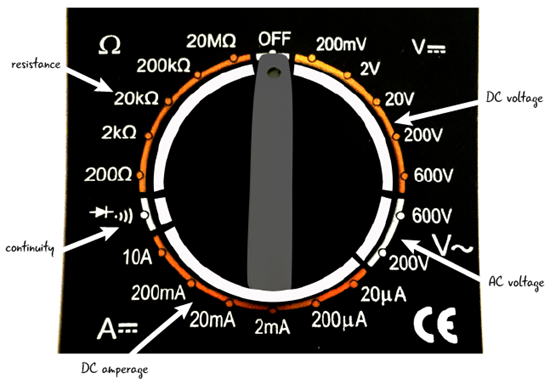
Similarly, for measuring current, you'll find ranges like 200mA, 2A, 20A, etc. Choose the range that can handle the expected current to avoid damaging the multimeter's internal fuse and circuits. Never try to measure current in the voltage measurement mode. Always set the range to the highest and only switch it to the required current range after powering off the circuit and connecting the probes.
Measuring resistance has its own range selection, and the process is similar. A typical multimeter may have resistance ranges like 200, 2k, 20k, 200k, 2M, and so on. Select the range that is closest to the resistance value you anticipate to get accurate readings.
Remember, choosing the appropriate range is crucial for obtaining accurate measurements and ensuring the safety of your multimeter.
If you select a ragne that is lesser than the value measured the meter will show "OL" symbol meaning overloaded , you have to move to the next higher range You will also see an "OL" when you're measuring continuity but the circuit is open or no connection.
Measuring Voltage
Let's start with one of the most common measurements: voltage. Voltage is the potential difference between two points in an electrical circuit. Measuring voltage is a fundamental skill that you'll frequently use in electronics and electrical work. You can measure both AC and DC voltages with a multimeter.
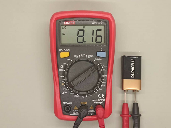
Follow these step-by-step instructions to measure voltage using your multimeter:
- Turn on the Multimeter: Turn on your multimeter and set the function selector switch to "V" for voltage measurement. If you are measuring DC voltage, use the "V" or "DCV" setting. For AC voltage, select the "V~" or "ACV" setting.
- Select the Range: Choose a voltage range that is equal to or higher than the voltage you expect to measure. If you're uncertain about the voltage level, start with the highest range and then work your way down to smaller ranges for more precision.
- Insert the Probes: Insert the red probe into the "VmA" or "V" jack and the black probe into the "COM" jack. Some multimeters have separate jacks for measuring AC and DC voltages.
- Touch the Probes: Touch the metal probe tips to the points between which you want to measure the voltage. Ensure a secure connection between the probes and the test points.
- Read the Display: Look at the multimeter's display, whether it's a digital numerical value or an analog needle on a scale. The measured voltage value will be indicated on the screen or scale.
- Take the Measurement: If you're using a digital multimeter, the measurement is usually displayed directly on the screen. If you're using an analog multimeter, read the voltage value from the scale where the needle points.
- Disconnect the Probes: After the measurement is complete, remove the probes from the circuit.
- Turn off the Multimeter: To conserve battery life, turn off the multimeter after use.
Keep in mind that when measuring voltage in a live circuit, be cautious and follow safety precautions to avoid electric shock. Always start with a higher voltage range, and if the reading is too low or unstable, switch to a lower range for a more accurate measurement.
Remember, safety first! Always assume that a circuit is live until you've verified that it's not. Use appropriate personal protective equipment (PPE) and follow safe measurement practices.
Measuring Current
Measuring current in a circuit is essential for various applications, from checking the operating current of a device to troubleshooting circuit problems. However, measuring current requires additional caution as improper connection can lead to circuit damage or blown fuses in the multimeter.
Follow these steps to safely measure current using your multimeter:
- Turn off the Circuit: Before measuring current, turn off the circuit or device in which you want to measure the current. This will prevent a surge of current from damaging the multimeter or the circuit.
- Select the Current Function: Set the function selector switch to the "A" or current measurement mode. Most multimeters have separate positions for measuring different current ranges, such as 200mA, 2A, or 20A.
- Choose the Proper Range: Select a current range that can handle the expected current. It's better to start with the highest range and then switch to smaller ranges if needed.
- Insert the Probes: Plug the red probe into the "A" or current jack and the black probe into the "COM" jack.
- Insert the Multimeter in Series: To measure current, the multimeter must be inserted in series with the circuit. This means breaking the circuit and connecting the multimeter in line with the current flow. For example, to measure current through a resistor, break the circuit, and place the multimeter probes in series with the resistor so that the current passes through the multimeter.
- Complete the Circuit: Close the circuit by turning on the power source or device. The current will flow through the multimeter and display the measured value on the screen.
- Read the Current Value: The multimeter will display the measured current value on the screen. If you're using an analog multimeter, read the value from the scale where the needle points.
- Interrupt the Circuit: After obtaining the measurement, turn off the circuit again and remove the multimeter from the series connection.
- Switch to a Higher Range: If the measured current exceeds the range you selected, the multimeter may show an overload indication (OL). In such a case, switch to a higher current range to get an accurate reading.
- Turn off the Multimeter: To preserve battery life, turn off the multimeter when you're done using it.
Always exercise caution when measuring current, as a wrong connection or excessive current can damage the multimeter and pose safety risks. Remember to set the range appropriately, and never attempt to measure current in a live circuit without proper precautions.
Measuring Resistance
Resistance measurement is valuable for identifying faulty components, verifying resistance values, and troubleshooting circuit issues. When measuring resistance, ensure that the component or circuit is not powered or connected to any voltage source.
Follow these steps to measure resistance using your multimeter:
- Turn off Power: Before measuring resistance, turn off any power source and disconnect the component or circuit from any active voltage source.
- Select the Resistance Function: Set the function selector switch to the "" or resistance mode.
- Choose the Range: Choose a resistance range that can accommodate the expected resistance value. Start with a higher range and then switch to lower ranges for more accuracy.
- Probe Placement: Insert the red probe into the "VmA" or "" jack and the black probe into the "COM" jack.
- Measure Resistance: Touch the probe tips across the component or circuit for which you want to measure the resistance. Make sure the probes have a good connection with the test points.
- Read the Value: The multimeter will display the measured resistance value on the screen or the analog scale. If you're using a digital multimeter, the value will be shown directly on the screen.
- Interpret the Reading: For analog multimeters, interpret the value based on the scale where the needle points. For digital multimeters, the resistance value will be directly displayed on the screen.
- Range Adjustment: If the resistance value exceeds the selected range, the multimeter may show an overload indication. In this case, switch to a higher resistance range.
- Disconnect the Probes: After the measurement, remove the probes from the component or circuit.
- Turn off the Multimeter: To save battery power, turn off the multimeter when you're done using it.
When measuring resistance, ensure that the component under test is isolated from any circuit or voltage source. If you measure resistance in a live circuit, the readings will be inaccurate and may damage the multimeter or the component.
A Practical Scenario: Troubleshooting a Power Supply
Let's take a practical scenario. Assume you are troubleshooting a power supply that is not working. To begin, you need to check the output voltage to see if it is really faulty.
To do this:
- Check if the power supply is a DC supply. If so, what voltage is it expected to output? Let's assume it's a 12V power supply. To measure it, we would put the meter in the Voltage measurement mode and in the 20V range. Since 12V is well below 20V, the "20V" range would be able to comfortably measure 12V. If we get no output voltage, we would check the power cord by switching the meter to the 250V AC range and check if the cord is providing AC power. If both of these are ok, then we would move to the internals of the power supply, checking for short circuits or burnt components.
To check for short circuits:
- First, power off the supply and discharge any capacitors. Then, move the selector to the "ohm" or continuity range and check for shorts. Shorts would show as very low resistances on the order of 1-2 ohms or beep in case of continuity function. Typically, the regulating elements and bulk current supplying transistors fail.
To check the transistors:
- We would need to select the diode range. The diode function, when connected correctly (Red probe to anode and Black probe to cathode), shows the voltage drop across a diode (typically 0.7 volts). A transistor is nothing but two diodes sandwiched together. A typical NPN transistor with three legs can be tested by checking the diode drop across the Base -> Emitter junction and the Collector -> Base junction. If both of them read around 0.7 volts on the forward direction and read "OL" (open loop) in the reverse direction, that means it's a good transistor. A faulty transistor would either read "OL" across both the junctions or 0 volts drop, meaning it's shorted internally.
Tips for Selecting a Good Multimeter
When buying a meter, if you have two meters in the same price range, always select the one with "higher count" over absolute accuracy. A higher count meter means it has more digits to display (more resolution). This is helpful as it can measure even very small changes.
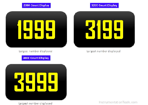
For example, a 4000 count meter can resolve up to 3999 values before moving to the next higher range. Say you're measuring a voltage in the range of 2 volts to 4 volts. A 4000 count meter can display from 2.000 till 3.999 before moving to the next higher voltage range. Whereas a 2000 count meter can only display till 1.9999, so in this case, it can only measure with one digit less resolution (2.00 till 3.99 only). Most cheap meters have only 2000 counts, but a few, like the multicomp pro series, give you 4000 counts.
The most useful functions for troubleshooting and using a multimeter are often the resistance/continuity functions and voltage ranges. When buying a meter, always choose one that has good voltage measurement accuracy and good resistance accuracy/continuity function. A meter with a high-speed latching continuity function will let you troubleshoot faulty connections, switches, and cracked PCBs very easily.
Many multimeters now come with a secondary bargraph display at the bottom of the screen. This is quite helpful to detect fluctuations and unstable values. The bargraph update frequency is generally much faster compared to the main display, hence anomalies can be quickly detected. For example, Fluke meters have a bargraph that updates 300 times compared to the main display, which only updates at 60Hz.
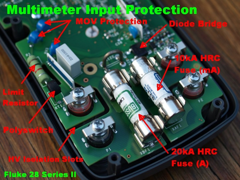
Safety is very important if you are going to do any mains voltage measurement. Most cheap meters have no internal protection other than a useless glass fuse. However, for a reasonable price, you can still get meters that have ceramic HRC (high rupture current) fuses as well as PTC (positive temperature coefficient) fuses. For example, some of the multicomp pro meters we stock have good protection and use HRC fuses at a very reasonable price.
The power source of all handheld meters is a battery, but the cheap ones often come with a 9V type battery. Not only is it expensive, but they also leak and last far less compared to standard AAA or AA batteries. A good meter will often have AA or AAA batteries as a power source, which is not only cheaper but also lasts longer.
